Category Archives: Tech Tips

Correctly testing and soldering guitar cables

Often poorly soldered or damaged guitar cables are the reason when the guitar signal sounds dull or too quiet. With an Ohm meter, the cables can be easily measured. But often guitar cables are not only soldered incorrectly, but also measured incorrectly. Therefore, I would like to explain you in this blog article how you test guitar cables properly and what you have to pay attention to when soldering the cable.

Testing guitar cables properly:

Testing guitar cables

Correctly testing guitar cables

  • The plugs must be on a non-conductive surface. A carpet is not suitable for measuring, because a carpet builds static charges.
  • Do not touch the plugs of your guitar cable nor the tips of the testing cables with your fingers. Otherwise you will measure the resistance of your own body.
  • The resistance between the tip of one plug and the tip of the other plug may be only a few Ohms. Ideally, the resistance is less than one Ohm.
  • The resistance between the sleeve (shield) of one plug and the sleeve of the other plug may be only a few Ohms. Ideally this resistance is less than one Ohm.
  • But the most important thing is – and most people do not measure it – the resistance between sleeve and tip. You just have to measure on one side of the guitar cable. This resistance should be infinite, meaning have no connection (open loop). Cables that were soldered incorrectly or too hot, or cables that are mechanically heavily loaded, can have a resistance here. If this resistance is near zero Ohms, then the cable has a short circuit. When the measurement is in kilo or mega Ohm range, the cable has a resistance, which can lead to dynamics, treble and volume losses.

Soldering guitar cables correctly:

Soldering Guitar Cable

Correctly Soldered Guitar Cable

  • Strip the outer covering of the cable, paying attention to the correct length (with Neutrik plugs, these are 2cm). Take care to not damage any braid of the shield.
  • Separate the braids of the shield from the center conductor and organize (twist) them into a single wire, thus resulting in a single conductor. Here you have to make sure that no individual braid sticks out.
  • If the shield has an additional aluminum foil, you have to cut off it (to the same length as the cable is stripped).
  • Depending on the connector type you use, the previously twisted shield conductor must be shorten. The screen must not touch the middle pin (signal conductor) of the plug in any way.
  • Strip the inner signal conductor of the cable only a little (3- 4mm) and also twist the braids.
  • Before you solder the cable to the connector, you must tin the the signal and shield conductors of the cable.
  • Also tin the solder joints of the plug previously.
  • Solder the shield first, and then the signal conductor.
  • And now the most important: DO NOT SOLDER TOO HOT and not too long! Make the solder on the plug just briefly liquid, then tuck the cable end immediately into it and wait to cool. You must work swiftly. Do NOT stick the cable to the plug while continue heating the solder for more than a second or two. The cable ends must not move during cooling down, otherwise it results in a so-called “cold joint”. The solder must be smooth and not completely frosted after cool down.

=> The plastic parts of the cable must not melt. Otherwise it may cause the above-mentioned resistance which results in signal loss.

IMPORTANT: There are also cables with conductive plastic, for example, Mogami. Here you have to observe the manufacturer’s instructions.

Here is a link to a Youtube video where everything is very well explained:
https://www.youtube.com/watch?v=nE9P67_E5N8

The Dry/Wet Guitar System

The Dry/Wet System: How Pros Run Their Guitar Rig.

The Dry / Wet system is a kind of stereo operation. But here, one speaker gets the guitar signal which only contains the basic effects such as distortion and WahWah (dry). The other speaker gets the signal with all the effects – especially reverb and delay (wet).

Dry Wet System

The Dry / Wet system: A very established principle!

A “real” stereo sound with lots of great effects is usually counterproductive in a live environment. If there is too much reverb, it becomes impossible for the sound engineer to mix a great guitar sound. It might sound good on stage, but the audience hears only squishy squashy tones since the concert hall comes with a lot of reverb itself.

However, if the FOH technician gets your dry signal in addition to the effect signal, he can work with the base sound and add only as much wet signal to the mix as necessary. Even stereo effects, such as PingPong Delays, only make sense when they are used very specifically and if your band works with an own sound engineer who exactly knows your sound.

The WET/DRY/WET system
If you nevertheless like to use stereo effects, you can go a step further and build a Wet/Dry/Wet system. This requires 3 cabinets and, besides your main guitar amplifier, a stereo power amplifier or two additional guitar amps. The center speaker gets the dry signal from your main guitar amp. The left and right speakers will get the stereo signal which is coming from your (multi-)effects unit.

Proper Power Supply for your Guitar Effects

Which is the proper power supply for my guitar effects?  What is voltage, what is the difference between AC and DC, and why do I have to care about currency and polarity?

When a guitar effect does not work, probably the most likely reason for this is that you are using the wrong power supply. When powering guitar effects, the following four electrical characteristics must be taken into account: the required voltage (V), the required current (mA), AC or DC and the polarity (in case of DC). If several devices are fed with a common power supply, there is also the issue of galvanic isolation.
A correctly labeled unit indicates the following information on the enclosure:

Guitar effects power supply labeling

Guitar effects power supply labeling

Unfortunately, not all manufacturers label their devices properly. However, a look into the users manual would have to promote the missing data.

Voltage (V)
Voltage (mesured in Volt) is the electrical potential between two points. If we compare electricity to water, voltage is like the water pressure. The pressure is there, waiting for the valve to open, allowing the water to flow. In contrast to water, the voltage does not flow into the “empty”, but only from one electrical pole to the other. Thus, voltage can only exists across or between two points (poles).

=> If the voltage of the power supply is too low, the guitar effect cannot work because it doesn’t get enough energy from the power supply.
=> If the voltage is too high, the effect may blow up because it cannot handle the amount of energy.

=> Voltage (V) of a power supply must always match the voltage of the device to be powered.

Current (mA)
Current is the amount of electrons that flow from one pole to the other. As long as the two points are “open”, no electricity flows. As soon as we connect the guitar effect to the power supply (or as soon as we switch it on), the electricity starts to flow from one pole through the effect to the other pole.
Back to our water analogy, current is the amount of water that flows through a pipe. The “mA”-value stated for a guitar effect is the max. amount of current the unit needs to operate. The “mA”-value printed on a power supply (e.g. Voodoo Lab pedal power) is the max. amount of current the psu can supply.
The power supply must be able to supply at least as much power as the effect device needs. It does not hurt, however, if the power supply can supply more (this is even an advantage). The opposite is quite bad. If the effect device requires more power than the power supply can deliver, the power supply “goes to its knees”, the voltage is “torn”. A regulated power supply switches off when there is an overload. This can either occur immediately or in the middle of the gig. A simple (unregulated) power supply simply ends up in a puff of smoke.
Analogue devices typically require very little current (less than 20mA), while digital devices require much more (several 100mA).

=> If a power supply is not capable to deliver the required amount of current, the guitar effect cannot work because it doesn’t get enough energy. Further, it can damage the power supply because the effect pedal demands too much energy.

=> Current (mA) of a power supply must at least match or better exceed the requirements of the device which you like to power.

AC/DC (Alternate Current / Direct Current) & Polarity
AC/DC is not only one of the world’s most famous rock bands, it is more an important electrical characteristic. The current, thus the electrons that flow in a cable, have a direction. A light bulb does not care in which direction the electrons flow. But most electronic components work only in one direction.
Most guitar effects work with direct current (DC). DC has a positive (+) and a negative (-) pole. These devices thus specify in which direction the current must flow. Therefore, the correct polarity (plus & minus) must be observed here too. Those units only work with correct connected polarity.
But there are also some guitar effects which require an alternating current (AC) power supply. Alternating current means that the polarity changes with the mains frequency (50Hz in Europe, 60Hz in America). Thus, the polarity does not matter when using an AC power supply. Guitar effects powered by AC have an integrated rectifier which converts the AC power to the DC power required for internal operation. These integrated rectifiers have some benefits which would be too technical to be explained here.

=> Guitar effects that require DC must be powered with a DC power supply. Further, you have to take care about polarity.
=> An effect that requires AC must always be powered with an AC power supply. There are also a few units that can be powered with AC and DC alike.
=> Powering DC guitar effects with an AC power supply can immediately destroy the unit. Powering an AC effect with DC will result that the effect pedal is not working
=> Always connect the proper (AC or DC) power supply. If using DC, make sure to have the correct polarity

Multiple power supply

Usually you have several effects which have to be supplied with power. On the one hand there are power supplies with several outputs. On the other hand, you can also use a simple power distribution cable with multiple plugs, which allows several effects to be connected to a single power supply. But here you must pay attention too!

Multiplug Power Distributuion Cable (Daisy Chain Cable)
You can feed several effects with the same power supply. If you have, for example, a power supply that says “9V DC 500mA”, and you have three guitar effects, one that needs 250mA, one that needs 100mA and another that needs 50mA, you can power all three effects with the same power supply. All three effects together require 400mA, the power supply can deliver 500mA. So enough for all three effects. However, a multiple power cable (daisy chain cable) may only be used if the following conditions are ALL met:

  •     All guitar effects require the same voltage.
  •     All effects require Direct Current (DC).
  •     All effects have the same polarity.
  •     All the effects together need no more power than the power supply can deliver
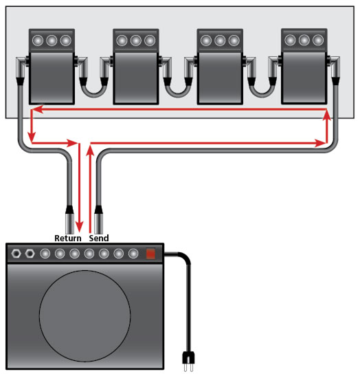
  •     The effects are arranged directly behind each other in the signal path.

=> Effect devices that are supplied with alternating current require a separate power supply each.
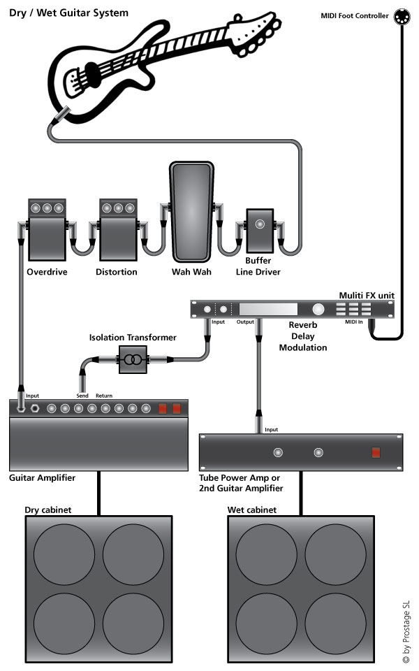
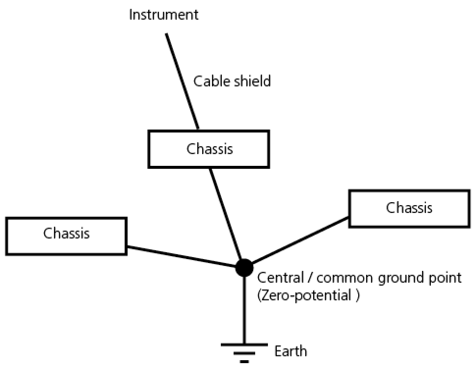
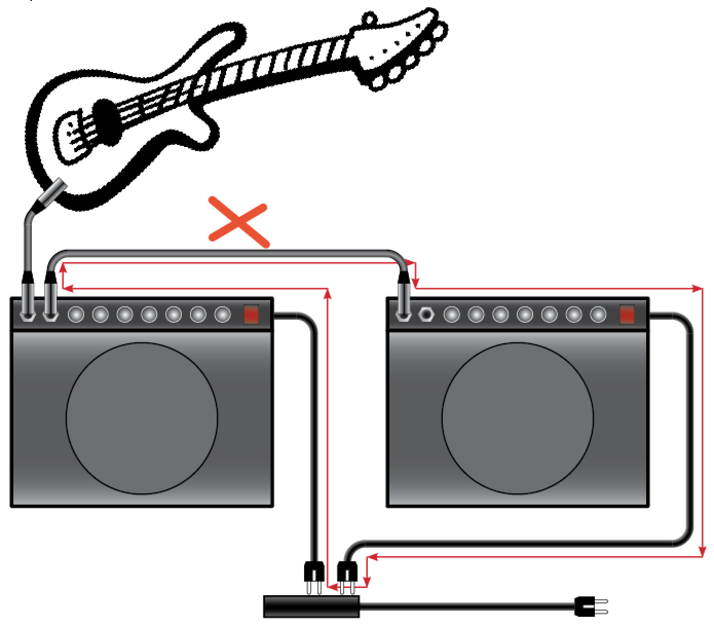
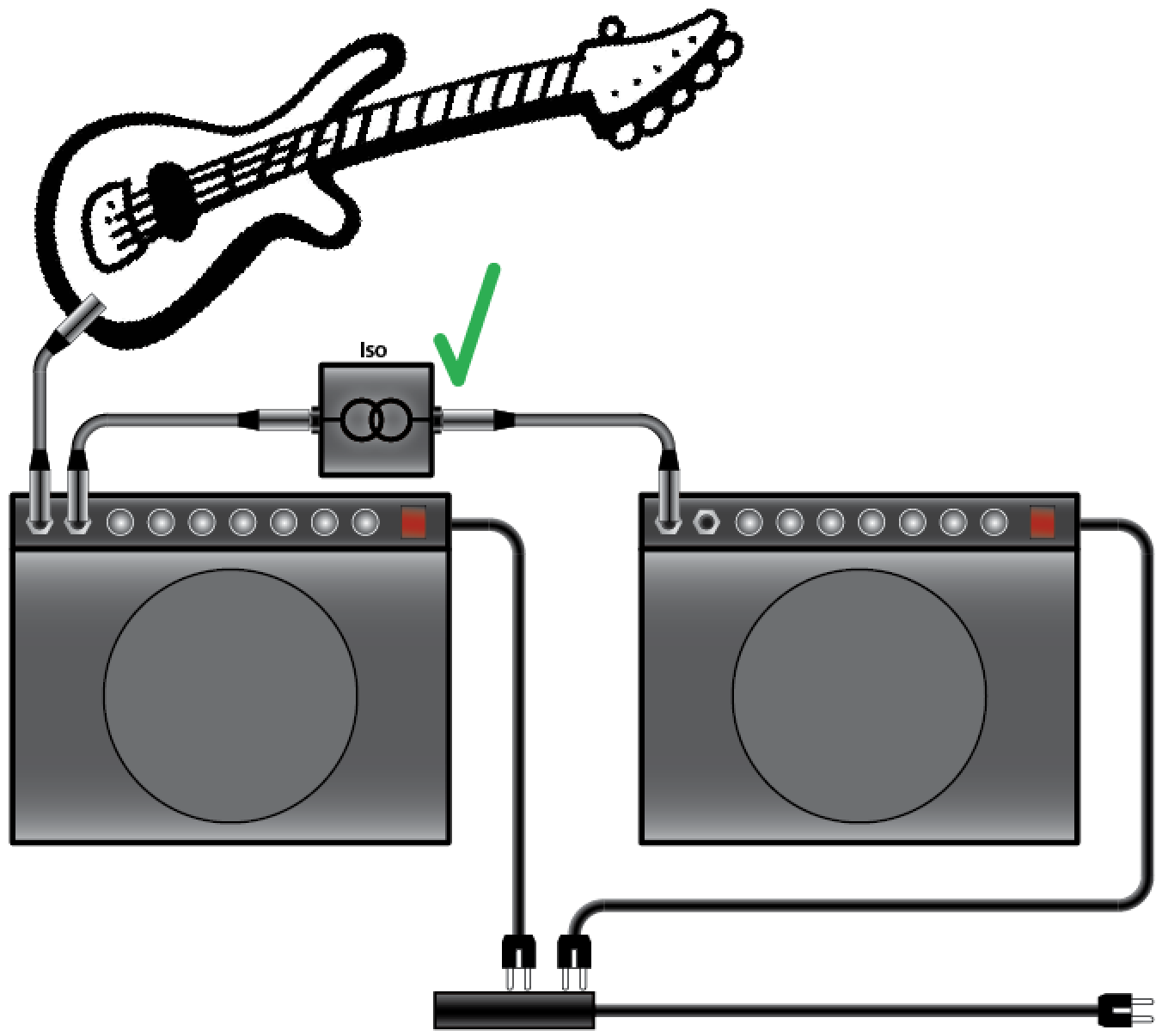
=> If there is an effect device in front of the amp, and another in send / return, they need separate power supplies. Otherwise, you would build a ground loop over the power cable, which will result in hum.

Multi Output Power Supplies
If you are using a power supply with several outputs, make sure that the outputs are galvanically isolated. This is the same like having several independent power supplies in one housing. You can then easily operate one effect device on each connector.
If the outputs are not galvanically isolated, it is simply a single power supply with multiple parallel connection sockets. This is the same as using a daisy chain cable and brings the above mentioned limitations and problems with it.

Choosing the right guitar effects power supply

Recapitulation: We have a power supply (the wall adapter) and a load (the guitar effects pedal). The power supply must provide the rated voltage (e.g. 9V DC). The effects pedal draws whatever current it needs. As long as the power supply can provide the current required by the effect pedal, everyone is happy and everything works. Things get murky if the power source can’t maintain the current, or if the voltage is too high or too low.

Troubleshooting

If you are having trouble powering your guitar effects, double-check if the current and voltage requirements by the effects pedal and the power supply match. Run through these steps:

1. If your effect pedal shipped with a wall adapter ex-works, try powering with the original power supply. If it powers up, it’s probably an issue with your third-party power supply, respectively, the used power supply is not suitable.

2. Check whether the power supply is AC or DC. Under no circumstances connect an AC power supply to an effect which must be supplied with DC, and not vice versa. Most effects are supplied with DC.

3. Check the polarity (DC power supplies only). Most guitar effects have a 2.1mm power connector with “center-negative” polarity. This unofficial standard was introduced by Boss many years ago. A “normal” power supply therefore fits with a “normal” effect.
However, a few manufacturers do it exactly the other way round (“center positive”). Further, there are also other plugs, e.g. Mini-jack or 2.5mm. Be sure to read the manufacturer’s specifications, where the positive and where the negative pole is. The polarity is often indicated by a symbol on the effects pedal. Incorrect polarity can damage the unit irreparably.

4. Check the voltage. Some guitar effects are very specific about their voltage requirements. If the effect pedal requires 9V, be sure not to send it more than 9V, because excessive voltage can irreparably damage the device. On the other hand, some pedals are perfectly happy running at anywhere from 9V to 18V. Just be sure you know what the manufacturer recommends.

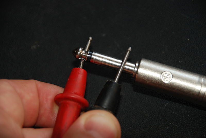
5. If you own a voltage meter, check if at the output of the power supply comes out what should come out, or if the device perhaps may be defective. Note: at an unregulated power supply, it is normal that the voltage reads 10-20% higher without a load connected.

6. Finaly, check the current. Make sure the power supply is capable of providing more current than the guitar effects pedal requires. For example, if your pedal requires 200 mA, it’s probably best to provide it at least 250 mA to ensure it works properly under all circumstances.

Now you’re a power genius and you know everything you need to know about powering your effects devices. For further information about building and wiring your guitar rig, get Prostage’s “Ultimate Guitar Rig Building Guide” with lots of tips & tricks how you prevent noise, hum and losses of transpareny & dynamics as well as lot of further valuable information.

Guitar Rig

Humfree Guitar Rig Wiring

Humfree guitar rig wiring is not easy. Hum can have many different causes. This article gives you the basic skills for properly wiring a guitar rig and will save you some headaches in your rig building adventure. For more detailed instructions, please download “The ultimate Guitar Rig Building Guide“.

Hum Caused by Ground Loops

Ground loops are certainly the most common reasons responsible for the hum. These are caused by double grounding connections. Thus, they have something to do with earth and cable shield. To understand and to get rid of ground loops, it is important to distinguish between “earth”, “chassis” and “cable shield”. But in a way, “earth”, “chassis” and “cable shield” are the same, because they are somehow connected. And the term “Somehow” is exactly the problem. To avoid ground loops, we need to know where “earth”, “chassis” and “cable shield” are connected. When wiring a guitar rig, we must be aware where we want them to merge.

Earth: (also called “ground”): The earth is, as the name suggests, the connection to the earth. This is the zero potential. In power cables, the connection to earth is called “grounding conductor”.

Chassis: If the chassis (housing) of a device is made of metal and the device is operated with mains voltage (120 / 240V), the housing must be grounded for safety reasons (the chassis is thus connected to earth within the device).

Cable Shield: The shield is used to keep electromagnetic fields from the audio signal. Within guitar cables, this is the outer, mostly braided conductor. In order that the cable shield can fulfill its function, it must be connected to earth.

Conclusion: Earth, Chassis and Cable Shield are always connected somewhere. To prevent hum by ground loops, it is important to know where they are connected.

Star-shaped Wiring
Basically, the connection of “Earth”, “Chassis” and “Cable Shield” must be structured like a star:

Humfree Guitar Rig Wiring requires a Star-shaped ground structure.

Star-shaped wiring

Triangle | Ring Wiring
If the star-shaped structure is not strictly observed and instead wiring is made in a triangle, the classic Ground Loop occurs. The problem is that the instrument is connected via two different paths to earth and the current can, therefore, flow through two different ways, respectively, the current can flow in a circle.

Hum caused by triangle wiring

Triangle wiring

Groundloop Caused by Split Guitar Signal

A typical example of such a triangle wiring is the use of two amplifiers. The following diagram shows a typical ground loop:

The typical ground loop using two Guitar Amps

Two Guitar Amps

In a guitar amp, the earth from the power cable and the shield of the guitar cable are connected both to the chassis. Thus, in our example, the guitar is grounded once through the amplifier on the left and once through the amplifier on the right. It does not matter whether the guitar signal is split by a Y-cable, or if the second amplifier is connected to the first amplifier.
Due to the cable resistances, the potential for the two amplifiers are quite minimally different (we are talking about millivolts). Therefore, along the line marked in red, a small current begins to flow in the circle. This is the Ground Loop!
This is audible as hum because this current flows with the mains frequency (50Hz in Europe, 60Hz in America). In addition, the harmonics (100 Hz, 200 Hz, ….  respectively 120 Hz, 240 Hz, …. ) are also generated. The longer the cables are, the bigger is the potential difference. As a result, the hum increases with the length of the cables.

Isolating Transformers to Prevent Ground Loops
In order to prevent ground loops, the connection of the guitar cable from one to the other amplifier must be separated using an isolating transformer. Inside an isolating transformer, there is no electric connection between input and output. The signal is transmitted magnetically instead. Transformers specifically made for guitars must be used (e.g. Lehle P-Split) so that the guitar signal is transmitted unaltered. Isolating transformers for studio applications are not suited for guitars.

Using an Isolation Transformator

Der Einsatz eines Übertragungs-Transformators

Groundloop over Daisy-Chain Power Supply

Another typical example of groundloops is powering the effects via daisy-chain cables or using a power supply with several outputs without galvanic isolation. Since the cables are usually very short, this hum is often inaudible.

Groundloop over Daisy-Chain Powercables

Groundloop over Daisy-Chain Powercables

Groundloop via Send-Return

Inserting effects in the Send/Return is also a groundloop. The longer the cables, the louder the hum. In order to avoid this hum, two approaches are possible:

  • Use an isolating transformer in either the send or the return line.
  • Do not use the 4-cable method to the pedalboard. Instead, connect the effects directly next to the amp with very short cables. If they must be switchable, use a MIDI controllable looper. The short cables also have the advantage to avoid dynamic and transparency losses.
Groundloop over Send/Return

Groundloop over Send/Return

More Information …

This was just a brief introduction to the main issue of hum. But hum can also be introduced by many other things, e.g. by interferences caused by lighting systems, computer monitors, fluorescent lights, nearby high-voltage lines and many other sources.
If you like to read all you need to know for successfully wiring a guitar rig, including a step-by-step instruction for trouble shooting, you can download “The ultimate Guitar Rig Building Guide” which explains everything in detail on over 30 pages.

MIDI over XLR Microphone Cable

StageWire - Sending MIDI data over XLR microphone cable

StageWire – Sending MIDI data over XLR microphone cable

Why using XLR Microphone cables for MIDI?

I did already retrofit MIDI foot controllers with XLR plugs in the 90′s. It requires just a few electronic components to send MIDI and phantom power over a single XLR microphone cable. But why did I do this? I have been touring with bands like Krokus and many others. For fast and reliable cabeling, I did need a solution that is road proof. XLR cables have many advantages over MIDI cables:

  • Safe and reliable connection between the foot controller and the effect rack
  • Extendable cord
  • Locked plugs
  • Spare cable available any time
  • Power supply and MIDI signal over the microphone cable

MIDI cables are OK for use in the studio and for wiring inside the guitar rack, but in my opinion, they are not suitable for running on stage.

However, the MIDI communication is  only unidirectional. This means, one unit talks (e.g. the foot controller) and the other is listening to it (e.g. the effects unit or the guitar amp). But what if you switch a channel on the amp itself and you like the MIDI foot controller’s state to change as well? That’s why we developed StageWire!

StageWire

StageWire is a consistent further development to send MIDI data over XLR cables. StageWire is a bus system. This means, every one talks to everyone. A Looper|Switcher can be interconnected with up to 14 MIDI foot controllers in daisy chain. Every unit can simultaneously talk and listen, all over a single microphone cable from device to device. Furthermore, the foot controllers are powered over the microphone cable! All units are in sync all the time. It does not matter on which unit you press a button.

StageWire was developed by Prostage and especially designed for rough use on stage. StageWire is four times faster than MIDI. Cable length may be up to 250m. Thus, you can send MIDI data over multicore-cables, e.g. to connect the FOH with the stage. The XLR connection guarantees, unlike the standard MIDI cables, a safe connection between foot controller and amplifier/effect rack. To connect StageWire with standard MIDI equipment, a MIDI XLR interface, such as the Prostage XTMpro, is required.

Well known manufacturers and rig builders such as Fractal Audio or Bob Bradshaw have applied this approach and now also build their foot controllers with 3-pin XLR connectors.